
- #2n3055 transistor datasheet pdf how to
- #2n3055 transistor datasheet pdf pdf
- #2n3055 transistor datasheet pdf download
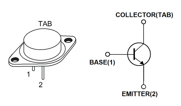
The collector is electrically connected to the case. 2016 2n3055 Transistor Amplifier Circuit Diagram Pdf.
#2n3055 transistor datasheet pdf how to
It is designed for general-purpose switching and amplifier applications. How to make audio Amplifier Transistor 2N3055 and MJ2955 500W StereoPCBA. STYLE 1 MARKING DIAGRAM Maximum ratings are those values beyond which device damage can occur. 2N3055 is a single diffused NPN silicon transistor in TO 3 case. W/☌ TJ, Tstg − 65 to +200 ☌ Operating and Storage Junction

Symbol Value Unit Collector−Emitter Voltage Rating VCEO 60 Vdc Collector−Emitter Voltage VCER 70 Vdc Collector−Base Voltage VCB 100 Vdc Emitter−Base Voltage VEB 7 Vdc IC 15 Adc Collector Current − Continuousīase Current IB 7 Adc Total Power Dissipation TC = 25☌ Comset Semiconductors, Epitaxial-Base NPN Transistor - PolNPN / PkgTO3 / Vceo60 / Ic15 / Hfe20min / fT(Hz)0.8M / Pwr(W)115, Original, PDF.

Pb−Free Packages are Available* MAXIMUM RATINGS DC Current Gain − hFE = 20−70 IC = 4 AdcĦ0 VOLTS, 115 WATTS VCE(sat) = 1.1 Vdc (Max) IC = 4 Adc 2N3055 Hoja de datos, 2N3055 datasheet, Microsemi Corporation - NPN POWER SILICON TRANSISTOR, Hoja Tcnica, 2N3055 pdf, dataark, wiki, arduino, regulador. BC547 Transistors equivalent BC549, BC636, BC639, 2N2222 TO-92, 2N2222 TO-18, 2N2369, 2N3055, 2N3904, 2N3906, 2SC5200 Short Description on BC547 BC547 is an NPN transistor so the manifold and emitter will be left.Features: DC Current Gain: hFE 20 70 IC 4A CollectorEmitter Saturation Voltage: VCE(sat) 1.1V (Max. Internal schematic diagram Features Low collector-emitter saturation voltage Complementary NPN - PNP transistors Applications General purpose Audio amplifier Description The devices are manufactured in planar technology with base island. General−purpose switching and amplifier applications. 2N3055 Silicon NPN Power Transistor Audio Power Amp, Medium Speed Switch TO3 Type Package Description: The 2N3055 is a silicon NPN transistor in a TO3 type case designed for general purpose switching and amplifier applications. 2N3055, MJ2955 Complementary power transistors Datasheet -production data Figure 1.
#2n3055 transistor datasheet pdf pdf
2SB778 DATASHEET PDF - 2SB PNP Planar Transistor (Audio Power Amplifier. 2N3055 NPN MJ2955 PNP COMPLEMENTARY SILICON POWER TRANSISTORS DESCRIPTION: The CENTRAL SEMICONDUCTOR 2N3055 and MJ2955 are complementary silicon power transistors manufactured by the epitaxial base process, mounted in a hermetically sealed metal case, designed for general purpose switching and amplifier applications. In this post we comprehensively discuss the pinout function, electrical specification, and application designs for the power transistor 2N3055. The 2N3055 is a power bipolar transistor designed to handle high power loads in the range of 100 V, and 15 amps. 2N3440 2N3439 2N2905 2N2222A 2N1613 2N930 2N3055 117 topics total. 2N3055 is one of the basic transistors available in the market for cheap and. 2N3055 Datasheet, Pinout, Application Circuits.
#2n3055 transistor datasheet pdf download
I recall a similar test report, where the old 2N3055 has been compared with modern parts of power devices (perhaps JLH-ClassA?) Unfortunately I have forget the download place in the web.Complementary silicon power transistors are designed for NPN power transistors, BD139 datasheet, BD139 circuit, BD139 data sheet. Perhaps one of the members can perform and investigate this. 2n3055 npn transistor bc547 npn pasangannya adalah bc557 pnp transistor bd139 npn. The test must perform by two modes: pure Class-A and Class AB (20-50mA through the output devices). Image : The texts in the PDF file : NPN general purpose transistors. Is a good topology therefore, if one remove the first stage of power buffer (please ignore the second schematic version). The schematic by the Densen-thread here about Thus, discussion like this are still present by this forum, but also in others.Īn easy way to find out an exactly attestation regarded different sonic quality (and different distortion measurement) through different ft's and different emitter structures would be to create a ordinary complementary push pull darlington power follower without front end for voltage gain in the NFB loop, so that only the NFB through the follower topology itself have an effect (open loop gain not too high). Or even so that nobody wants to use such methods of measurement. This is one package pinout of 2N3055,If you need more pinouts please download 2N3055s pdf datasheet. Unfortunately, it is so, that nobody uses such measuring methods. In case of the traditional measuring methodes (THD 1000 Hz, IM 19/20KHz) you are right.īut with the appropriate measurements, I would get a fairly accurate statement about the amp sound character without having heard him oneself.


 0 kommentar(er)
